SP-1 Steering setup
So over the past couple of months, I’ve been racing a SpeedPassion SP-1 in the F1 classes here. Now it’s taken a little while for me to get my head round it, as it’s my first link style F1 car, having previously I raced a 104 X1 and WGP.
Have to say, from the start, even with the kit setup the car has been good, with the main changes I’ve made only to the roll damper (going to hard damper greese), and side springs (to the softest tamiya one from the RM01). The car has been good enough to TQ and win at the local club, as well as having some great close racing.
Still, I wasn’t happy with the front end setup of the car. The kit instructions aren’t overly clear on how best to setup the front of the car for 190mm rubber tyres, with most of the instructions specific to a 200mm foam tyre setup (as is predominantly run in most of asia).
Now the main issue with the front end, is that to set the ride height, the wishbone mounts are shimmed upwards. However, this doesn’t move the steering rack, as this is mounted to the lower plate, that the wishbones also mount too. This then presents an issue where simply raising the wishbones, gives a lot of upwards angle to the steering links, or in otherwords, bump toe-out. I’ve never found this desirable, on any type of car, be it F1, TC or other. On the 104’s, I ran the upright servo setup, just to get rid of that effect.
Anyway, moving onto the point of this post… I’ve spent a bit of time phaffing around with the front end over the past few evenings, trying out different options to reduce the bump steer. And this is what I’ve come up with.
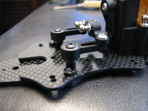
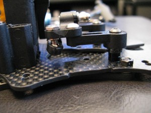
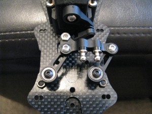
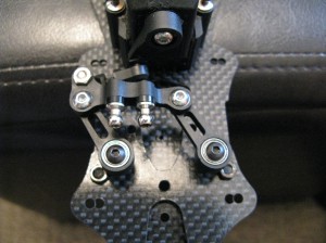
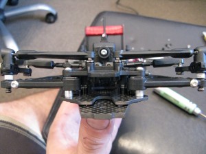
What I’ve done here, is raise the steering posts up using 4mm worth of shims (not forgetting using a longer screw!), and also flipped the steering bellcranks upside down from the kit setup. This raises the rack by about 6mm, which is great for reducing the angle of the links.. but..
Raising the rack that much, starts to have interference problems with servo horn, as the drag link position would be in the completely the wrong place keeping the ball on the top of the rack. So, the solution I’ve gone with is to mount the drag link underneath the rack. The other option is to mount the servo with the horn horizontal, and shim the link down… but I couldn’t be bothered to take the servo out!
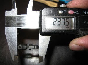
Whilst I was at it, I thought I’d have a look at the drag link, as I had noticed before that the left-right steering angles weren’t the same. Now I know some would adjust the EPA on the transmitter to compensate, but my OCD doesn’t allow for that. It has to be mechanically right, so I set to work to get the links in the right place. Making the link longer (to 23.75mm vs the kit 21.5mm), and mounting the servo horn off centre gave very similar left to right.
And with that all done, the final setup is a lot closer to how I feel it should be set up. I should note that I have 4.5mm of shims under the arms to get the ride height I’m after, and also have a 2mm shim under the rear upper ball as well, as this position doesn’t get raised when you raise the arm, and that affects castor. You can also just see the angled servo horn.
However the proof is in the driving, and it will be a few weeks before I get a chance to test out the changes, so I’ll report back then… still, looks better on the bench 🙂

