May18 Update Part 2 – More Carbon bits
Carrying on from Part 1 of the May Updates, Here is Part 2.
I’ll continue on the carbon parts theme, and run through most of the other parts I’ve worked on recently.
Top Decks
Now obviously, the standard kit MTC1 top deck is pretty unique, being a split design that has a pivot ball mounted front section. This certainly seems to have a place, and is a good tuning option. It seems that the ultra flex tends to take away steering, which seems more suited to high-speed, high grip tracks.
So, for the majority of the time, I have run conventional one piece designs. In the lower traction conditions, they react better, and are more consistent. And whilst I was pleased with how the Mugen one-piece worked, I felt more could be gotten from it.
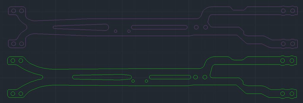
The main area I wasn’t happy with, was on the front bulkhead mounting. The standard part is effectively T-shaped, which seems to act more as a brace across the bulkheads than actually flexing as a top deck should. In effect, it’s more a central pivot point.
So, breaking out the CAD again, I revised the shape based off of other known designs. As you can see in the above image, there is much more of a V than a T shape, and the central slots have also been adjusted as well. The rear section is exactly the same.
This allows the front end of the car to twist more progressively. On track, there was a surprisingly big difference. Car steered smoother, was more consistent, and overall faster. A total win, and honestly something I wasn’t expecting.
One thing to note though… I only mount the top deck at the front in the front two holes. Why? Well, if you look carefully, you’ll see that the holes line up differently to the bulkheads in the front compared to the rear. The bulkheads have 3 screw holes, so the rearmost screw holes at the rear of the top deck are in the equivalent place where the front upper arm screw mounts are.
So by using all four front screw holes, the front of the top deck is mounted a little closer to the centre of the car than the rear mounting, which I feel stiffens the front. So by using just the front screw holes, you have it mounted the same as the rear, and a smoother car. It’s a quick thing to test, but worth it.
Rear Shock Tower
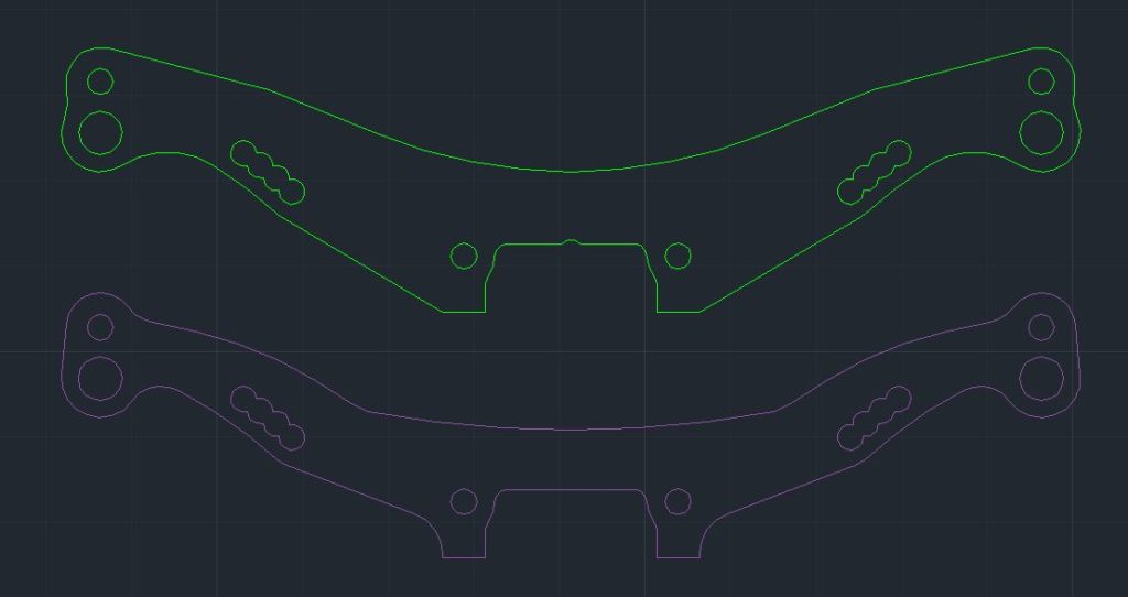
The standard tower is well known to be pretty flexible, as the shape is quite thin in some areas, and you can easily feel it when you have the car in your hands. This can stop the shocks doing what they are meant to do, as the tower flexes, rather than the shocks moving.
This one was a pretty simple and easy fix… as Paul at Bezerk already had the part designed up 🙂 Literally a little bit of reshaping to add more material, and with the same thickness, much stiffer.
Result was an improved, more consistent feel on track, with a hair more rear bite. A very subtle improvement, but probably be a bigger gain on higher grip tracks.
Bulkhead raisers
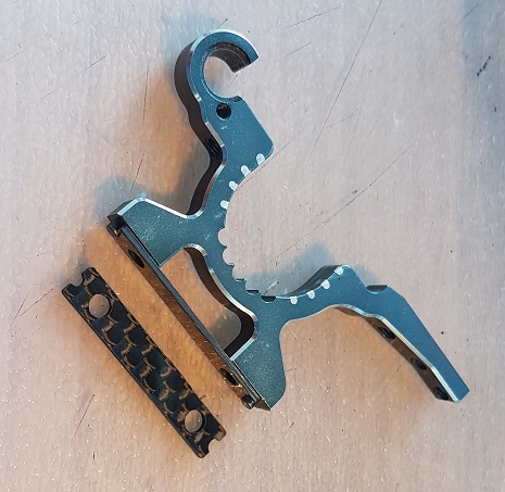
One other part I have had made up (and this comes further into play in part 3), was some small 1mm thick shim plates to raise the axle bulkheads. The idea here is to move the diff axles a little higher, with a flatter dog bone angle. From some of my other posts, you may know that I’m a fan of running the diffs high. In our conditions, low just feels too stuck, and lacks corner speed. Higher is harder to drive, but generally frees the car up and is faster.
It’s not all to do with the CoG, but also the driveshaft angle. A lowered diff won’t roll as much, but will also have a much larger angle on the driveshaft. An angled driveshaft will try and flatten out when it rotates, which unloads that end of the car. From experience, high diffs end to have more forward traction (braking and acceleration), but with less mid corner grip.
The MTC1 diffs in the low position are very low, and in the high, still about (you guessed it) 1mm lower than other cars high positions. Hence the spacers to bring the diff axles into the preferred angle range. And the locating pins still (just) engage…
Now this does also affect a few other points on setting on the car.
The camber link positions are 1mm higher, so then need 1mm less shims in those positions. Also it raises the shocks up 1mm… so combined with the above rear towers, I had a lowered set made up to compensate. So shocks still in exactly the same position, despite the raised bulkheads.
This actually was a more subtle change than I expected. A little freer again compared to Low v High diffs, and a small improvement in laptime. The bigger benefit is that it allows for a bit more clearance underneath for larger pulleys (See part 3)
Servo Mount and Battery Tabs
These last two parts aren’t really performance parts, but more of making the car easier to work on, and a look a bit neater.
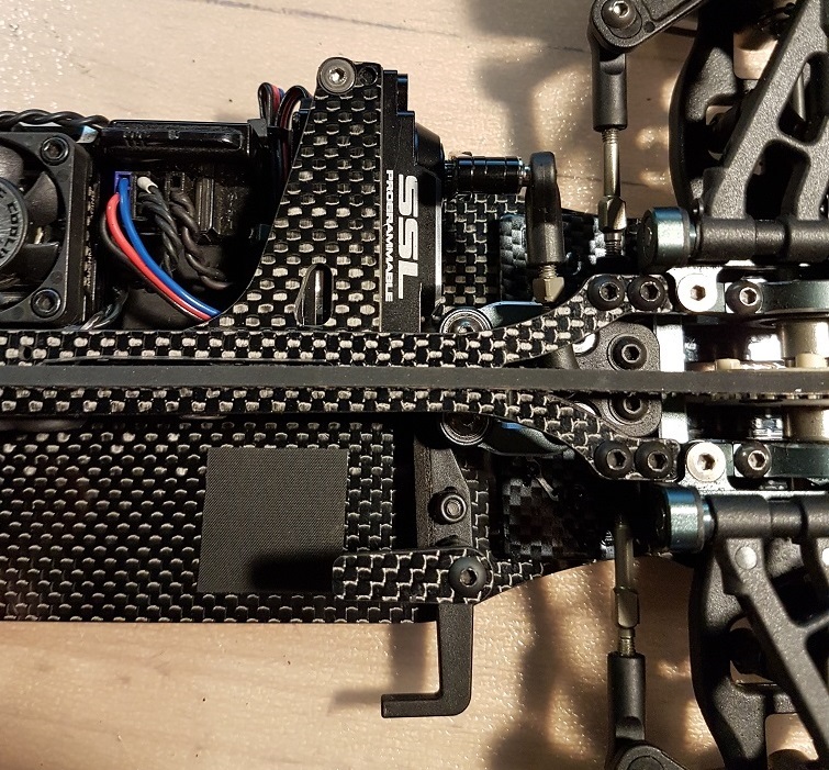
I’m not a fan of the floating steering, never use it outdoors as IMO it takes away steering feel. So, for neatness, had a new servo mount top plate that removes that option, and looks a lot neater to boot 🙂
The other part I’ve added is a tapeless battery mount. I hate tape! I used some 15mm aluminium standoffs, and some small carbon plates, a few screws and spacers to get the right heights, and has worked awesome. However, I have to admit to really liking the look of the recently released Mugen setup (A2413 – Battery Mount Optional), which might get added to my cars later 😉
And that pretty much covers Part 2 of the update!
Look out for Part 3 soon, as I’ll be moving onto the bigger pulley conversion I’ve been working on…


