May18 Update Part 1 – Chassis plates
It’s been a few months since my previous post, and a lot has changed recently… been working hard on nailing down options on the Mugen that I personally feel improve the car. I’m gonna do this update in a couple of parts, to avoid going too long with the posts…
Now I was meaning to do a video blog for ease (and probably will still try to.. if so will link it in later), but actually just wanted to have a bit of a brain dump first and work from there.
So anyway, since the last update, I have had a few big meetings under the belt. First up was the Queensland State titles, held at the excellent New England Park raceway. All in all it was a great showing for Mugen Seiki Australia, with Jeff Hammon taking the win in ITSC Modified, and Pete Beckett the win in ISTC 13.5t. Further to that, MTC1’s were the most numerous in both A-finals, 3 in Modified (including yours truly) and 4 in ISTC 13.5t.
Personally, I was very happy with how the weekend progressed. Started out with the setup I had run at XRS, with a couple of updated carbon parts (will come back to that shortly), and worked mainly on power and braking, as well as small alterations to geometry. Also took the opportunity to compare the bodyshells as well. Managed to qualify 9th in ISTC modified, and after a bit of luck in the finals, progressed up one spot to finish 8th.
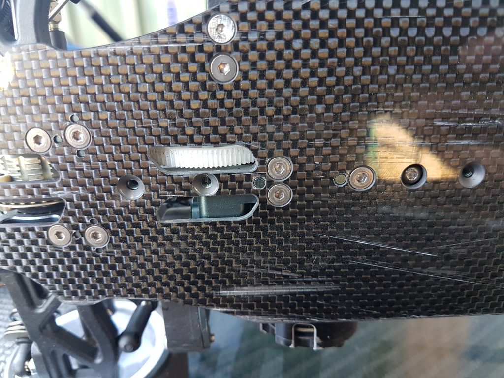
Next up was the XRS round 3 (I skipped round 2 being away on hols in Europe) down at the Kambah track in the ACT. Moving into the winter months now, it was a lot cooler conditions, so had to work to adapt my setup a bit. Saturday wasn’t so great, what seemed like an innocuous glance on a steel barrier ripping a screw the bottom of the chassis plate. This lost a bit of track time, and I struggled to make up for it. Managed to qualify 3rd on the sunday, and ended up 3rd, although the finals got cut short due to rain. But overall, car has been working well.. and the developments I’ll delve into next.
Chassis Flex
The first item I’ve been playing with in development has been the flex of the car. From the outset, I’ve had my concerns with the shapes of the chassis, top and rear shock tower. These parts were the first in my sights to have a play with. Now I’m only going to talk chassis for the time being, as that’s the biggest area. Look out for the top-deck and shock towers in part 2.
As a side note, Paul over at Bezerk RC has been my go to for cutting carbon parts. Good quality, and excellent speedy service.
Chassis Plates
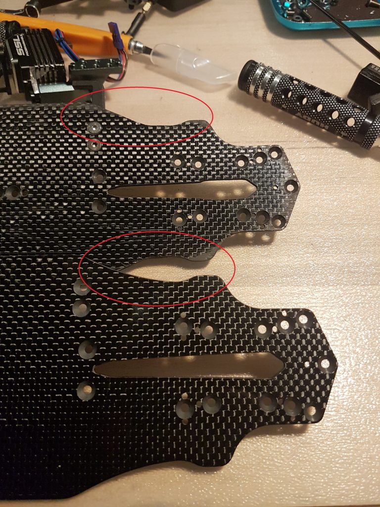
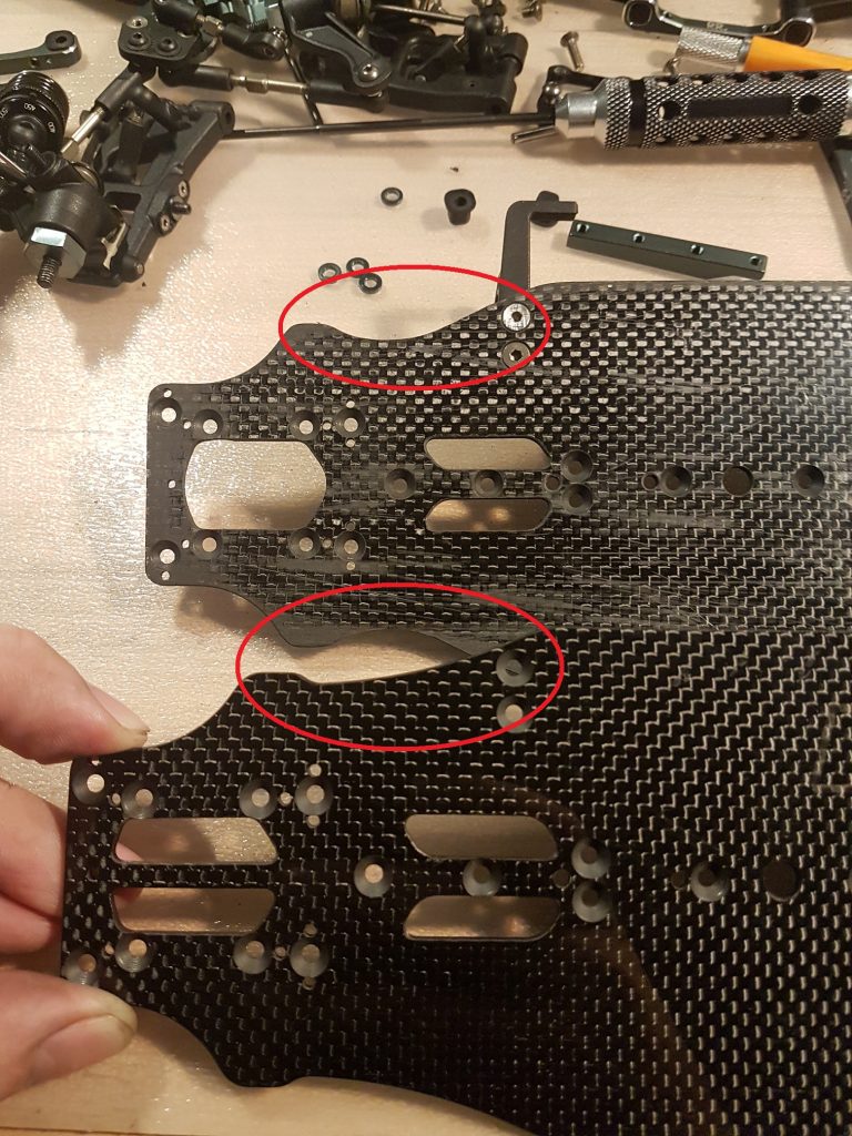
In my opinion, the chassis plate as standard is a bit unconventional, and from previous ‘projects’ I know that the shape can be critical to getting a car right. Overlaying the standard chassis with Xray and Yokomo, you can clearly see the difference between them and the MTC1 plate.
My main concern is the areas circled in red, the chassis cut outs, which is areas where the chassis does a lot of it’s flexing. On the MTC1, the front section is too narrow, and elongated, whilst the rear also cut’s in far too much. Too much flex can be a bad thing, it can make the car feel inconsistent, and actually loose grip as it unloads. I was finding that to get the car even remotely settled, I would have to always run the rear most motor mount screw (the one that needs the 1mm spacer) to lock the rear down as much as possible. Even then, it would still get snappy.
Chassis V1
So to test out my theory, I started out having a Yokomo style chassis made up, as this, IMO, is the car that is closest to the Mugen. You can see the differences between Standard and V1 in the image below (standard in purple, V1 in green);
The shape has been adapted from the BD8 shape, but keeping the ears for the droop screws. I also made an adjustment to the diff cut-outs, elongating the one under the front diff, and splitting the rear into two. I also took the opportunity to remove the outer set of servo mount holes (I only use the central ones), and moved the steering posts back 1mm to allow for a different range for the Ackerman.
In testing, I followed my usual pattern, and to back to backed the two plates. Here having two cars was a complete saviour, and avoided any need to do a dreaded track side chassis swap. Straight away it was obvious that the V1 was more consistent, and gave a lot more mid corner grip. Gone was the occasionally snappy rear end behaviour, replaced with it being very locked in, too much so in fact. I spent a few meetings experimenting with the V1, trying to free the car up more, even going to extremes of removing two sets of rear most motor mount screws (see below), but still couldn’t quite get the balance where I wanted.
So I went drastic, and broke out the dremel to hand adjust the chassis….
Chassis V1.5
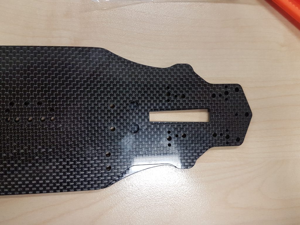
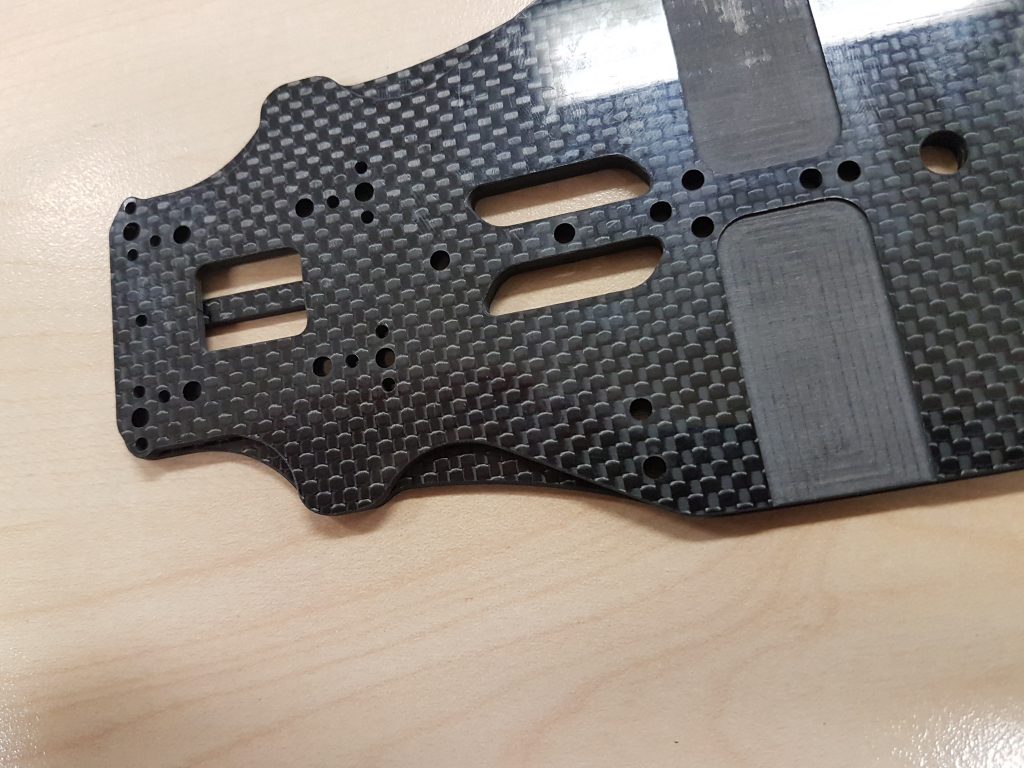
.. and so V1 became V1.5! This moved the chassis design more to a T4 shape, which has a deeper rear flex point, positioned more forward, and the front flex point further rearward. It was achieved by printing out an outline copy of the T4, sticking to the V1, and then carefully using a sanding wheel to get to the shape needed. I also removed the rear diff cut out brace, to try and encourage a little more flex (and the fact that with the diff in the low position, the pulley would hit the brace…oops)/ Looking at the pictures, you can see the difference between the V1 and V1.5.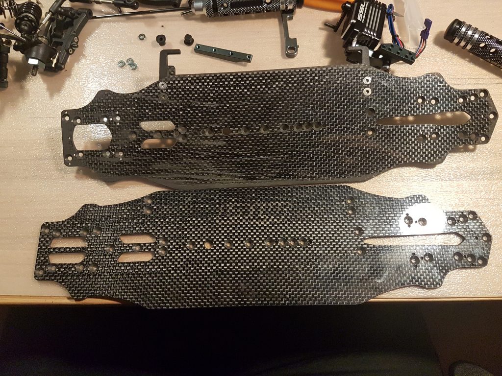
V1 vs V1.5
On track…now we were talking. The deeper rear cut helped to unlock the rear (but not to the inconsistent level of the standard plate), and the car was much easier to drive and more consistent. I couldn’t obviously back to back with a V1 (the V1 in the pictures has some errors meaning I couldn’t mount it properly), but overall the feel was much improved, and lap-times supported that assessment. Combined with the revised top deck (more on that in part 2) the balance was really good, and how I like a car to feel.
Chassis V2
So with the hand-adjusted version proven the right path, I decided that a properly cut version was needed, so I broke out the trusty CAD. V2 was influenced by the T4 shape, although I moved the rear flex point forward 5mm or so, to try and keep the flex points in the same place relative to the suspension mounts as on the Xray. I also shortened the front diff cut out, and made the rear one a little smaller.
I also elected to have the motor recesses cut a little deeper compared to the V1, leaving only 0.5mm under the motor, rather than the 1.5 or so of the Standard plate. I actually was in a bit of a panic to get this in time for the QLD titles, so bolted it on the car straight away with zero testing and ran with it for that event. I didn’t give it much thought at the time, but after the event, something didn’t feel quite ‘right’ with the car. Really hard to put a finger on, but seemed less settled, and not quite as good as the V1.5.
Somewhat unfortunately, I did get the opportunity to test V1.5 and V2 back to back at the ACT XRS round as mentioned before. Having pulled a screw through the V2, I mounted the V1.5 back onto the car. And the balance was better, more settled, and consistent. Seems the small changes for the V2 hadn’t worked as intended, with the thinner recess and moved rear flex point making the car a little worse to drive. So onto V3…
Chassis V3
This is which is basically a properly cut version of the V1.5, with the rear flex point moved further back. Did take the opportunity to further refine the diff cuts, and tweak the battery mount screw holes to remove some play. Also specified the motor recess to be less deep than V2 (1mm thick), to add a bit more meat back in that area.
On track, the V1.5 feeling was back. Car has a lovely balance, with good, but not extreme rear rotation. Also has consistency, with a positive but not overly aggressive front, albeit this is also in conjunction with the revised 1pc top decks (see Part2).
So for the moment, this is what I’m happy with, a worthy improvement, IMO, to the MTC1.
And that’s it for part 1… I’ll follow up shortly with Part 2, that will be all about the other stuff I’ve been trialling!


